자동차의 기능 테스트를 보다 효과적으로 측정 할 수 있게 지원하는 전문 솔루션입니다.

주요 사업
분석
통신 인터페이스
계측
차량 시험
엔지니어링 서비스
CANmod.input : 8채널 아날로그/디지털/주파수 to CAN 컨버터

해당 제품은 8채널의 아날로그,디지털 및 주파수 데이터 계측을 제공합니다. 계측된 데이터는 CAN으로 출력되며, PC 없이 Stand-alone 으로 사용 가능합니다.
Description
해당 제품은 8채널의 아날로그, 디지털 및 주파수 데이터 계측을 제공합니다. 계측된 데이터는 CAN으로 출력되며, PC 없이 Stand-alone으로 사용 가능합니다.
이 장비는 높은 정확도 및 높음 샘플링 속도를 제공하고 있으며 입력 범위 및 디지털 데이터를 위한 임계 값 등을 설정할 수 있습니다.
사용자는 해당 제품을 차량 네트워크 혹은 CAN Interface와 같은 CAN bus에 통합하여 사용 가능합니다. 예를 들면 사용자는 해당 제품을 CSS Electronics 사 CANedge 제품과 함께 사용할 수 있습니다.
FEATURES
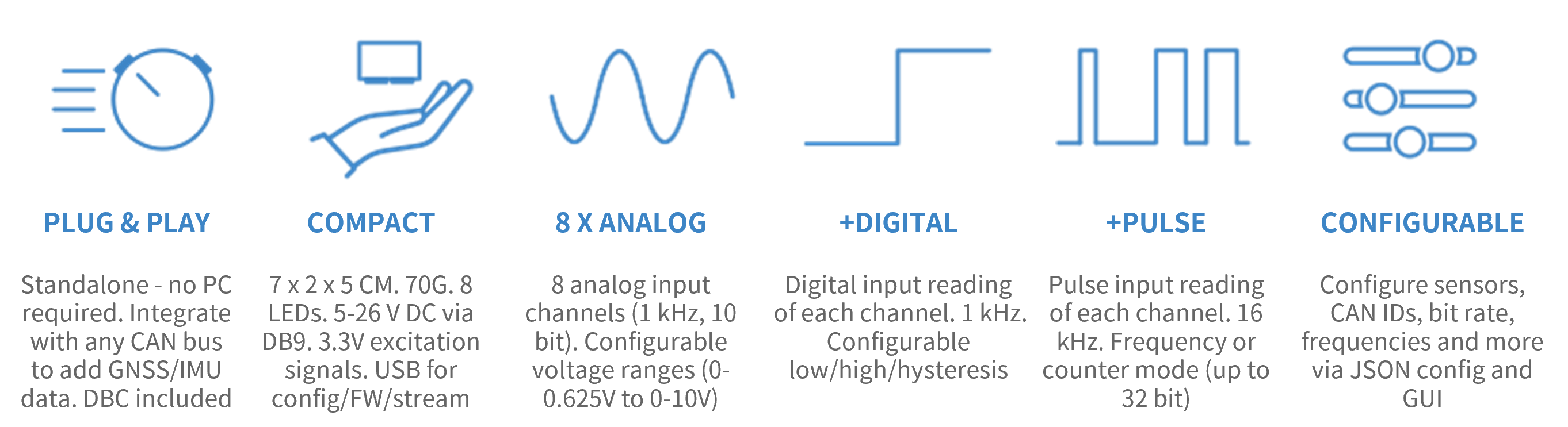
CAN 통신을 이용한 아날로그/디지털/주파수 데이터 계측 지원

8개의 채널을 이용하여 아날로그/디지털/주파수 데이터를 손쉽게 CAN bus로 추가할 수 있습니다.
l 최적의 계측을 위한 입력 범위 설정 기능 지원
l 디지털 데이터 계측을 위한 임계값 설정 기능 지원
l CAN-FD 줄력 기능 지원(Optional)
l 병렬운영 지원(16,24,32..채널)
l 센서 전원 입력을 위한 전원 출력 기능 지원(~3.3V)
l 병렬운영 가능(8,12,16…채널)
l 5-26VDC 입력전원 지원
l 데이터 확인을 위한 DBC 파일 지원
Example: Log/stream sensor data
| GENERAL | |
| Functionality | The device produces analog/digital/pulse data from 8 input sensors and outputs via CAN/USB |
| Included | CANmod.input module and USB dust cover (input sensors and mini USB adapter not included) |
| Firmware | Supports free firmware updates via USB for adding features |
| Configuration | Configuration files based on the popular open source JSON schema concept (similar to the CANedge) |
| Software | Free open source editor tool for easy device configuration (offline/online version available) |
| Safety | CE, FCC, IC and RoHS certified (see the Docs for certificates) |
| Warranty | 1-year warranty |
| Support | Free, fast & high quality support |
| Origin | Denmark |
| SENSOR (input) | |
| Channels | Supports 8 input channels |
| Sensor Types | All 8 input channels support analog, digital and pulse-type sensors |
| Sampling Method | Each input channel samples both the analog, digital and pulse signal of the connected sensor |
| Input Range | Configurable input ranges (0-10V, 0-5V, 0-2.5V, 0-1.25V, 0-0.625V) |
| Range modification is useful e.g. for optimizing quantization resolution and signal amplification | |
| The input channels share input ranges in pairs of two (CH1/CH2, CH3/CH4, CH5/CH6, CH7/CH8) | |
| Resolution | 10 bit |
| Sampling Frequency | Analog inputs: 1 kHz | Digital: 1 kHz | Pulse (frequency/counter): 16 kHz |
| Digital Thresholds | Configurable digital high/low switch thresholds (0-100%) incl. optional dead-zone/hysteresis |
| Pulse Modes | Pulse inputs can be measured as frequencies (reset) or counters (accumulate) |
| Pulse Resolution | Up to 32 bit (4,294,967,294) |
| Protection | Sensor inputs are protected against overvoltage & undervoltage conditions |
| Input Impedance | 136K |
| DATA PARAMETERS | |
| CAN Signals | The module ouputs sensor data via CAN messages/signals (for a full list, see the Docs or DBC file) |
| Analog measurements are output in millivolt (mV) [1000 Hz] | |
| Digital measurements are output as 'actual' (dead-zone, low, high) and 'low'/'high' signals [1000 Hz] | |
| Pulse measurements are output as a frequency/counter value (for reset/accumulate mode) [1000 Hz] | |
| Note: Limits apply to the practical output frequency depending on baud rate, message count etc. | |
| CAN BUS | |
| Channels | 1 x CAN channel |
| Modes | The device can either broadcast the data onto the CAN bus - or provide it on-request |
| Standard | ISO 11898: Compliant with CAN (between 5K and 1 Mbit/s baud rates) and CAN FD (1M, 2M, 4M) |
| Identifiers | Compliant with CAN specifications 2.0A (11-Bit ID) and 2.0B (29-Bit ID) |
| Termination | Termination can be toggled via switch below DB9 connector |
| Retransmission | Retransmission of frames that have lost arbitration or been disturbed by errors |
| Transceiver Protection | Protection: +/- 25kV HBM ESD, +/-12kV IEC ESD, +/-14 V bus fault, short circuit |
| Common mode input voltage: +/-12V | |
| TXD dominant timeout (prevents network blocking in the event of a failure) | |
| CONFIGURATION | |
| Bit Rate | Select between standard bit rates (5K to 1M) or use custom bit-timing |
| Enable/Disable | Individually enable/disable each CAN message |
| Identifier Customization | Individually configure each CAN ID (11-bit or 29-bit) |
| Push/Poll Mode | Individually configure 'trigger' modes for each CAN message (push or poll) |
| Frequency | Individually configure prescaling of each CAN message frequency to lower rates |
| ELECTRICAL | |
| Input Supply | +5V to +26V DC via the DB9 connector (power via pin 1 or pin 9) |
| Alternatively power via USB (for updating firmware/config or for streaming data in real-time) | |
| Power Consumption | Extremely low (<1W) - no risk of battery drainage |
| Protection | Reverse voltage protection on CAN-bus supply |
| Transient voltage event protection on supply lines | |
| MECHANICAL | |
| Enclosure & Weight | Compact aluminium enclosure: 52.5 x 70.0 x 24.5 mm (L x W x H), 70 grams |
| Connector (Front) | 1 x Standard D-sub 9 (DB9) connector |
| Connector (Back) | 1 x D-sub 25 (DB25) connector |
| Sensor Supply | Dedicated excitation signals for each channel (~3.3 V, shared max of 100 mA) |
| Pin-Out | See the product manual for the DB9/DB25 connector pin-outs |
| USB | Standard mini USB connector for config/firmware updates and streaming (USB cable not included) |
| LEDs | Module status via 8 external LEDs: Power, CAN bus, Memory, Status, CH1/CH2, CH3/CH4, CH5/CH6, CH7/CH8 |
| Temperature | Operating temperature (CANmod.input module): -25degC to +70degC |
| IP Rating | IP Rating 40 |
| Mounting | Module can be mounted via e.g. rugged double-sided tape, zip-ties or a mounting bracket |
